
Margin & Edge Decisions For Flawless Plotter Feeding & Zero Material Snags
Optimize mechanical boundary clearances, prevent roller collisions, and balance tight nesting density against reliable automated cutting tolerances.
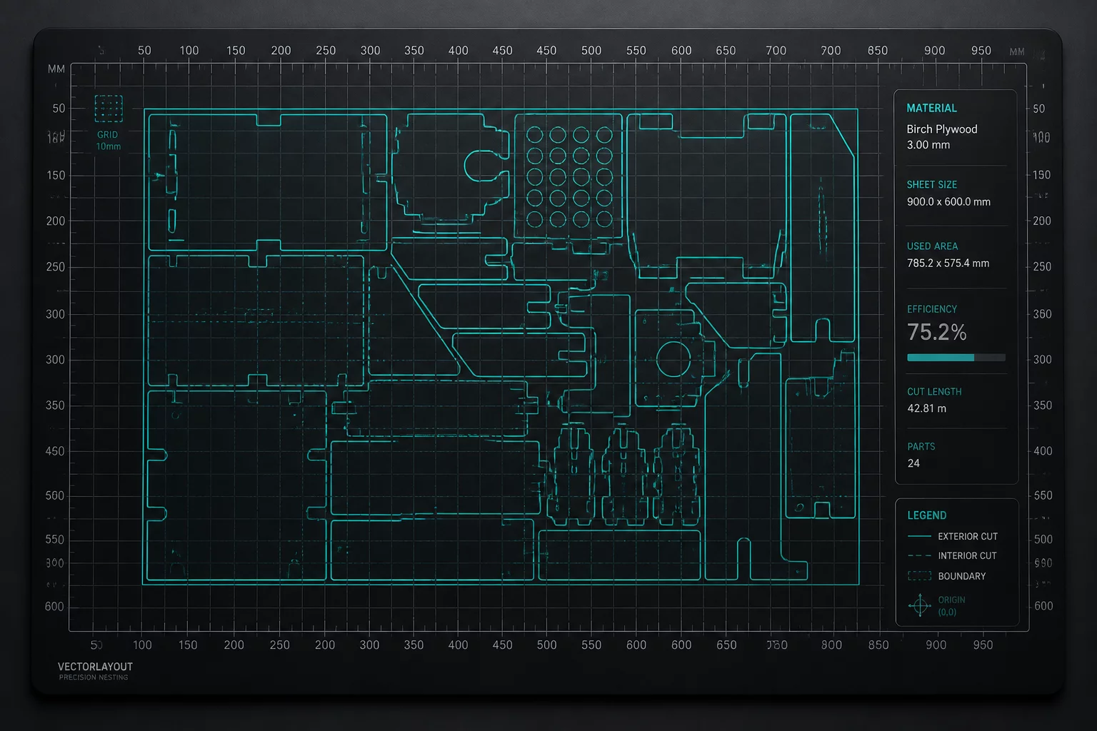
Mastering Spacing Between Cut Geometry & Sheet Boundaries
Prevent edge drag, pinch roller deformation, and registration mark misreads by calculating exact mechanical clearances across vinyl, cardstock, and thermal films.
Grip & Roller Bounds
Pinch Zone: 12-18mmPlotter pinch rollers apply constant downward pressure. Placing cut vectors inside the direct roller travel path causes vinyl wrinkling, track misalignments, and blade gouging.
Inter-Piece Kerf
Safety Gap: 2.5-4.0mmBlade rotation radius (offset) drags the material slightly at sharp direction turns. Insufficient space between neighboring contours causes tearing of delicate interior details during cutting.
Optical Sensor Margins
Clear Zone: 15-20mmPrint & Cut registration marks require pristine background contrast. Stray graphics or excessive bleed intrusion into sensor scan lanes triggers read failure alarms and aborted jobs.
Rectangular Margin & Spacing Preview
Planning example for rectangular pieces only. Counts use the entered sheet and piece dimensions, margin, and spacing. Area coverage is geometric coverage, not a measured material-saving claim; verify the layout and orientation in your cutting software.
Adjust your media dimensions, outer mechanical buffer, and inter-item kerf spacing to inspect live net cuttable yield and edge boundary health in real-time.
Material-Specific Spacing Guidelines
Different substrates react uniquely to blade friction, static build-up, and roller gripping forces. Calibrate your software offset per raw material grade:
- Adhesive Craft & Sign Vinyl (651 / 631)Keep minimum 10mm top/bottom edge margin on cutting mats; 2.0mm inter-cut gap prevents backing sheet score throughs.
- Heat Transfer Vinyl (HTV / Iron-on)Requires 12mm leading margin to avoid edge curl under the carrier sheet during high-speed weed box scoring.
- Cardstock & Heavy Paperboard (200-300 gsm)Allow at least 3.5mm between cuts to avoid structural tearing along fibrous grain directions.
Common Margin Failure Modes & Quick Fixes
Symptom: Vinyl lifting & bunching at sheet edges
Roller CollisionFix: Expand outer perimeter margins by 5mm or shift artwork inside the dedicated grid bounding box in your software.
Symptom: Sensor skips bottom registration marks
Optical ShadowFix: Maintain minimum 20mm bottom margin on sheet end to allow the optical eye room for forward and backward passes.
Symptom: Snagged letters during weed box peel
Zero Kerf OverlapFix: Implement a 1.5mm offset boundary with automated nesting margin offsets to isolate each decal geometry cleanly.
Explore Practical Layout Strategies
Expand your nesting efficiency toolkit with our dedicated guides covering mixed-size nesting, repeat sets, and CAD/CAM setup.
Silhouette Studio Layout
Step-by-step registration marks and cut boundary configurations.
Repeat Sets
High-speed matrix array duplication for commercial batches.
Mixed Sizes Nesting
Interlocking heterogeneous polygons to salvage negative scrap area.
Orientation Cases
Analyzing grain bias, feed direction, and rotation tolerances.