Arranging Mixed Sizes & Heterogeneous Cut Pieces
Master the art of packing large silhouette anchors alongside micro-stickers and secondary decals on a single cutting bed without sacrificing speed or material yield.
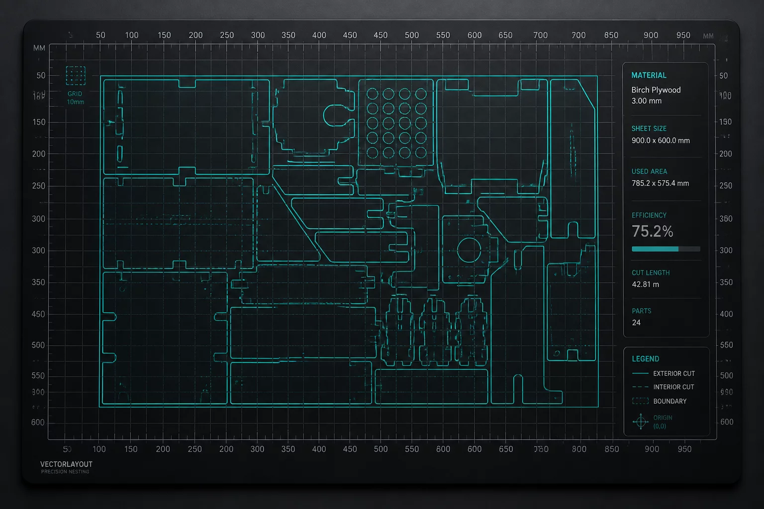
Three Ways to Arrange Mixed Sizes
Compare the same large panels, medium tags, and small labels inside a limited material boundary. Consider orientation, spacing, groups, and the way pieces will be handled after cutting.
Largest-First Infill (NFDH)
Establish structural anchors by placing oversized geometries first along safe reference edges inside the material boundary, reserving interior voids for secondary micro-elements.
Negative Space Infill
Exploit hollow counter-spaces, interior loops, and irregular concave borders within large silhouettes to pack small stickers and utility tags without enlarging the overall bounding box.
Zoned Blade Guiding
Segment mixed layouts into rapid-pass micro-zones and intricate detail sectors to equalize cutting blade wear and mitigate carrier-sheet distortion during high-speed vector passes.
Compare Three Mixed-Size Layouts
Pieces: two 90 × 90 mm panels, three 50 × 40 mm tags, and eight 20 × 20 mm labels. Material: 300 × 300 mm. Keep a 12 mm edge margin and at least 8 mm between pieces. All artwork stays upright. What should move, group, or repeat before cutting?
- Layout priority
- Compact footprint
- Orientation
- Upright · 0°
- Edge margin / spacing
- 12 mm / at least 8 mm
- After the cut
- Sort pieces after cutting
Each option contains the same 13 pieces. This is a dimensioned arrangement example; it does not calculate machine runtime or claim a percentage of material savings.
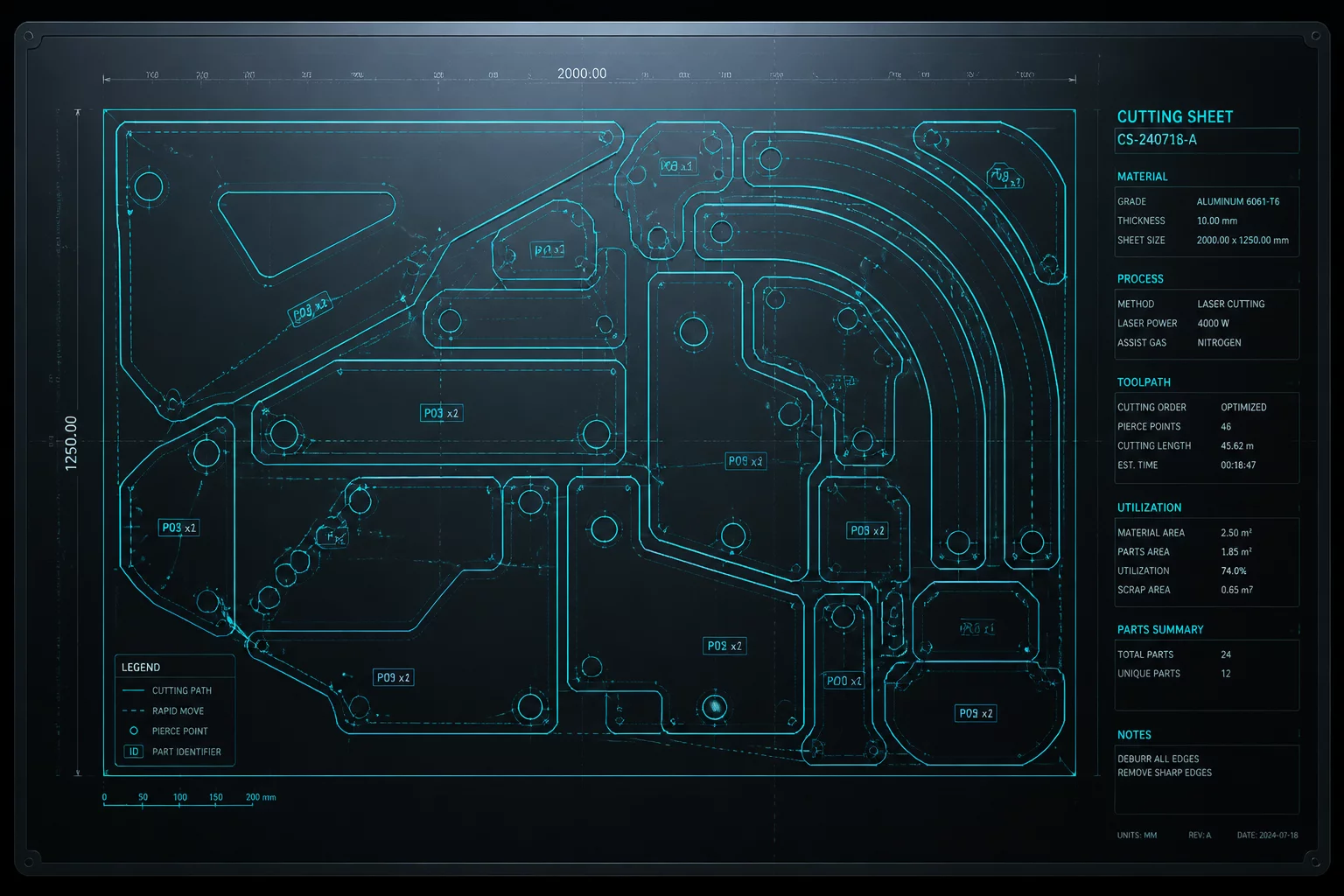
Best Practices for Combining Varied Scales
- Group by Minimum Blade Clearance: Always maintain safety buffers proportional to workpiece dimensions. Explore our Margin Decisions guide to calibrate cut boundaries.
- Prioritize Grain & Orientation: Maintain uniform anisotropic fiber or brushed-metal angles across differing sizes as detailed in our Orientation Cases.
- Batch Repeated Multi-Packs: Group fixed sets before filling remaining edges using methods from Repeat Sets and Production Sets.
Ready to Master Multi-Size Plotter Setups?
Review hands-on software steps inside our Silhouette Studio tutorial or compare cutting tool precision in our equipment breakdown.
Silhouette America identifies advanced nesting and multi-cutter support as Business Edition features. Official edition information.