
Mixed Geometric Shapes Challenge
Nesting distinct irregular polygons alongside circles and right triangles on a single flat substrate to achieve maximum material yield without causing toolhead collisions or edge tearing.
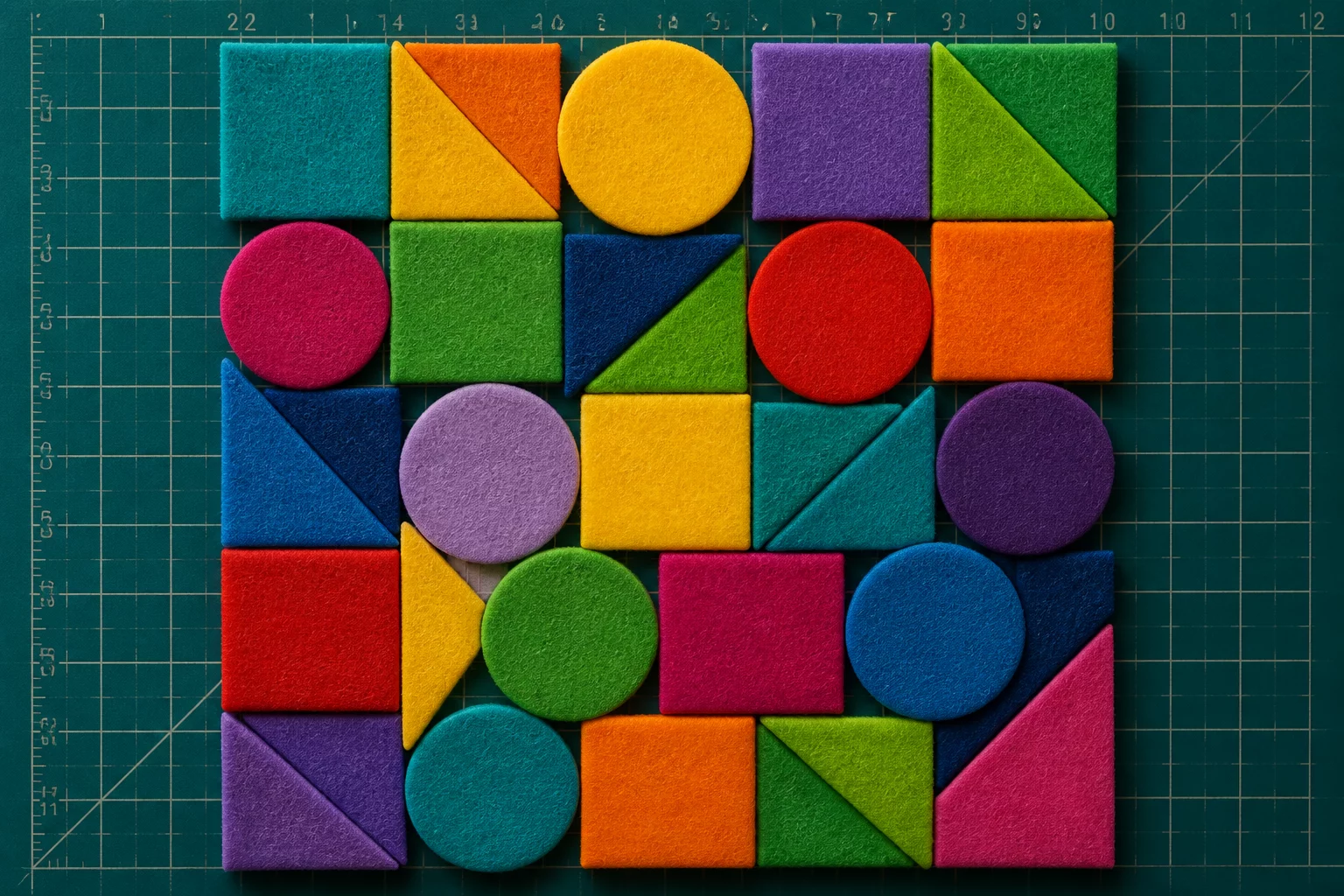
01 Geometry Hierarchy & Perimeter Assignment
Nesting mixed geometries introduces distinct spatial friction compared to uniform rectangular decals. When acute triangles, circular discs, and asymmetrical polygons share one cut area, standard bounding box algorithms waste vast areas in between. By placing the largest complex polygons first along rigid sheet borders, you establish stable anchor zones across the whole cut boundary.
Secondary components possessing rotational symmetry, such as discs and small isosceles triangles, should fill the leftover negative pockets around primary contours. This hierarchical nesting sequence prevents uneven margin buildup and keeps blade travel predictable along clustered tangential lines.
Fit right-angled triangles directly against outer material corners before placing circles. Angular points lock cleanly into sheet perimeters where rounded shapes waste unused corner material.
Algorithmic Contour Nesting Decisions
Compare placement, material direction, spacing, and post-cut handling using your actual pieces and sheet boundary.
02 Managing Tangent Clearances & Cut Vibration
Sharp acute corners positioned directly adjacent to curved circular outlines cause severe stress concentrations during fast blade movement. When the plotter head changes direction abruptly between dissimilar geometries, vacuum hold-down pressure can drop around localized cut lines, creating sheet lift and ragged cuts.
Maintaining a reliable 3.5 mm boundary margin between contrasting contours preserves sheet rigidity. Aligning parallel cut segments into contiguous toolpath groups reduces total head travel distance and prevents rapid acceleration spikes that compromise cutting accuracy.
Beware of mechanical overcut loops on acute internal vertices. An overlapping knife arc can clip neighboring circular perimeters if spacing falls below 2.5 mm.
Compare placement, material direction, spacing, and post-cut handling using your actual pieces and sheet boundary.
03 Execution Protocols for High-Yield Production Runs
Validate your nested cutting job by running a non-cutting dry trace across outer sheet borders before sending the full job. This dry pass guarantees that rotating polygonal components do not stray into pinch roller zones or cross machine registration mark boundaries.
Always arrange components by geometric complexity: anchor large asymmetric polygons first, then rotate small symmetrical shapes in 15-degree steps to seal internal voids.
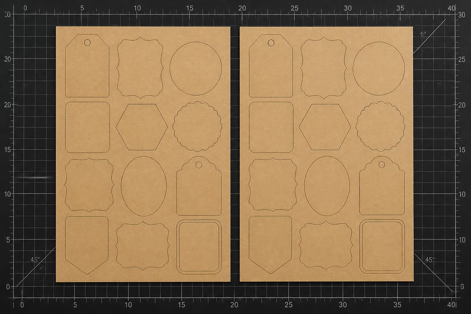
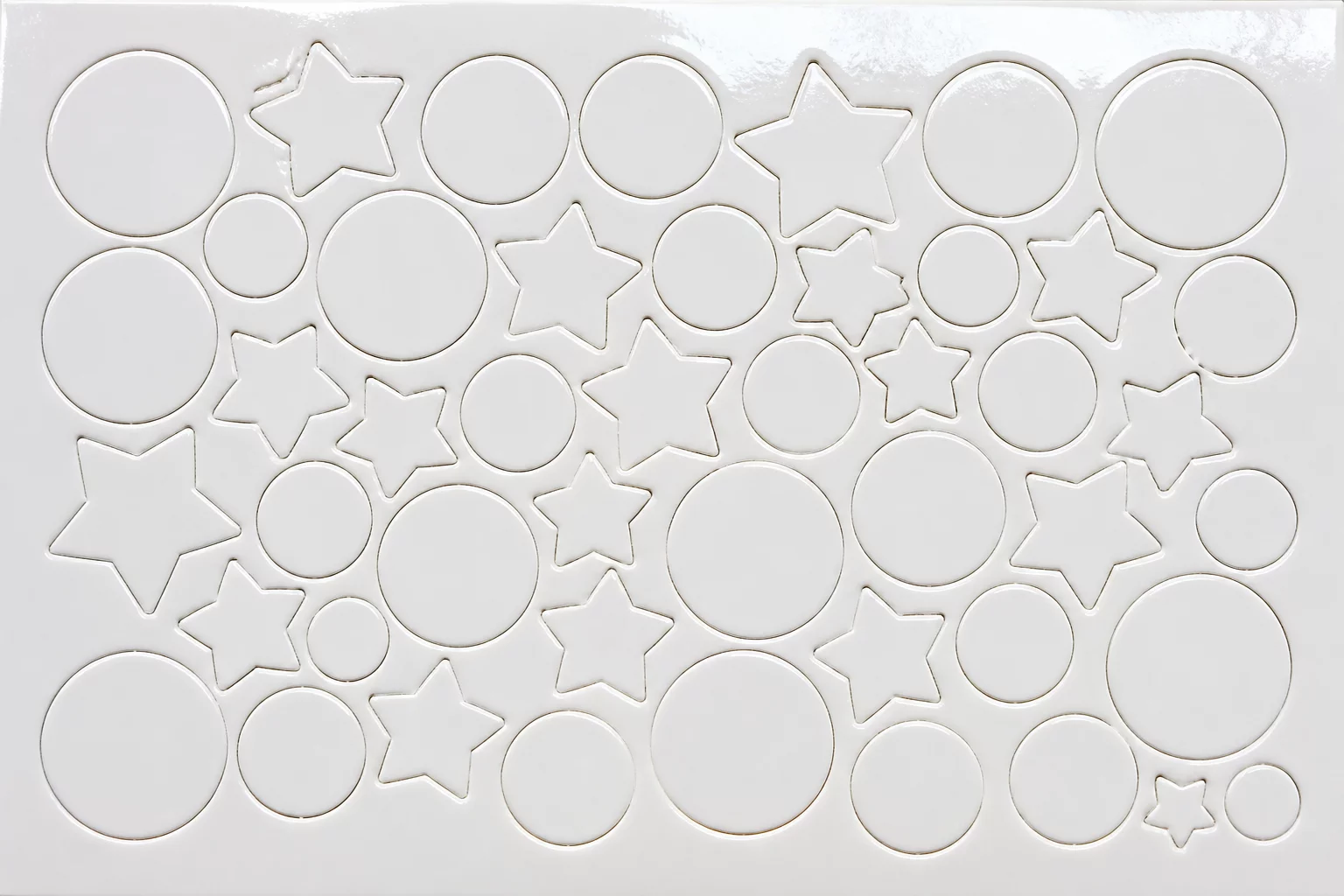
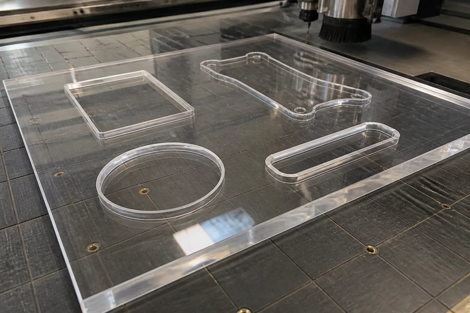
Workshop Feedback & Results
Leave Your Workshop Result