
Rigid Material Spacing Challenge
When cutting dense acrylic, thick styrene, or rigid boards, tight nesting causes thermal warping, mechanical chatter, and edge fractures. Discover how to calculate safety spacing without sacrificing batch yield.
01 Understanding Kerf and Thermal Clearance in Rigid Media
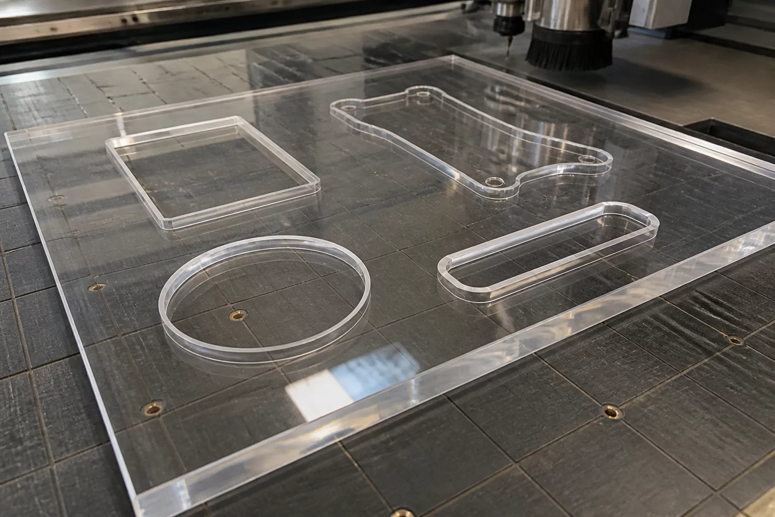
Rigid substrates behave drastically differently from flexible vinyl or standard paper cardstock. When an oscillating blade, drag knife, or milling bit passes through dense acrylic and heavy polymers, friction transfers significant thermal energy into surrounding material boundaries. Cutting adjacent parts too close together allows heat to accumulate along narrow bridges, leading to melted edges, micro-fractures, and compromised dimensional accuracy.
The physical kerf of your cutting tool defines the absolute baseline clearance. While standard vinyl requires mere tenths of a millimeter between cut paths, rigid sheet processing demands a minimum buffer equal to twice the material thickness plus tool diameter. This clearance preserves structural integrity across the scrap skeleton so the sheet remains firmly locked under vacuum hold-down.
Always execute a two-square test cut with your chosen bit or heavy-duty blade. Measure inner and outer dimensions with digital calipers to dial in the exact toolpath offset in your nesting software before packing production sheets.
Optimize Step-Over Distances in Silhouette Studio
Learn how to adjust perimeter margins, nesting spacing parameters, and cut sequences for dense media workflows.
02 Vibration Dampening and Vacuum Hold-Down Integrity
Dense substrates exert heavy lateral resistance against the cutter. As a blade or bit travels around intricate curves, high-frequency mechanical vibration ripples across the plate. Narrow material webs between parts resonate and chatter, creating rough stepped edges and occasional premature part ejection from the bed.
Maintaining robust web bridges between nested contours ensures vacuum pressure stays evenly distributed. When individual parts are spaced at least 8 millimeters apart, the surrounding matrix maintains enough surface area to resist uplift forces generated by high-speed directional passes.
Thin bridges under 4mm on 3mm+ acrylic frequently snap mid-job, jamming cutter heads and ruining entire sheets.
Compare placement, material direction, spacing, and post-cut handling using your actual pieces and sheet boundary.
03 Lead-In Placement and Sequential Cutting Logic
Where the cutting tool plunges into the substrate dictates the stress concentration point on every part. Always place plunge points and lead-ins on external waste channels rather than part contours. In tandem, sequence cuts from the interior hollows outward, preserving outer frame rigidity until the final perimeter passes are completed.
Prioritize structural stability and heat dissipation over aggressive micro-nesting. Generous spacing protects edge finish, reduces tool wear, and eliminates catastrophic part lift during unattended high-speed cutting.
Workshop Feedback & Results
Leave Your Workshop Result