
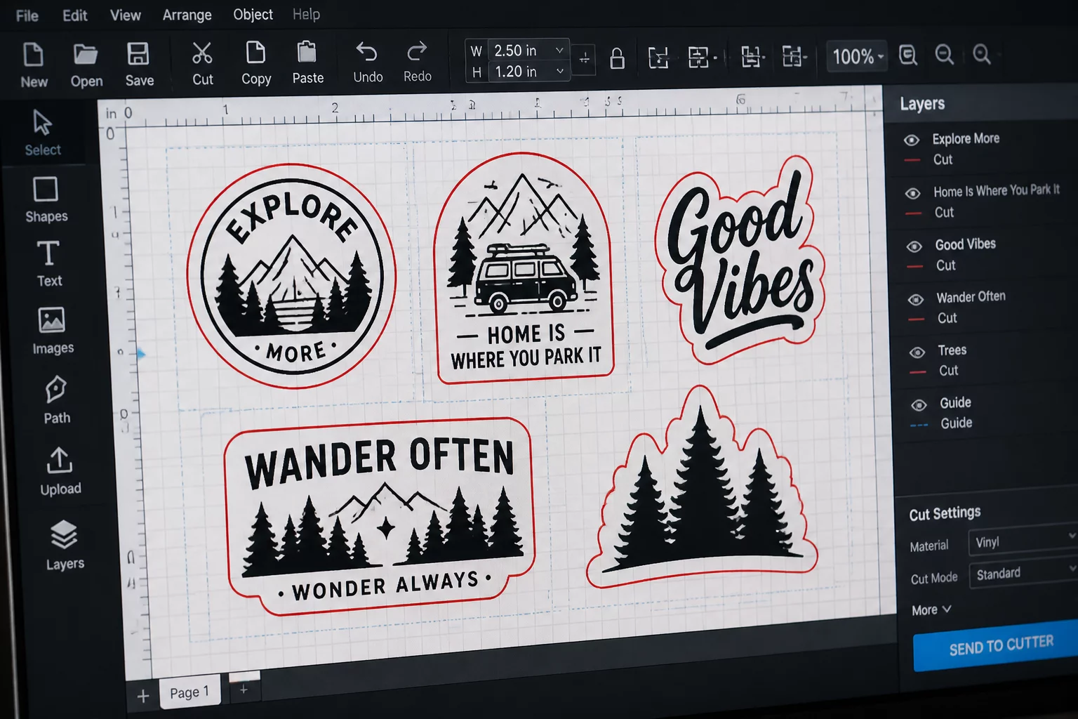
Distinguishing Print Borders from Active Cutting Limits
Silhouette Studio displays two distinct boundary perimeters on your virtual cutting mat. The gray print border reflects the physical driver limits of your desktop printer, whereas the red cut line marks the mechanical boundary reachable by the plotter carriage. Placing vector paths across the red cut border causes the software to truncate toolpaths automatically without warning during job execution.
Opening the Page Setup panel reveals essential toggles for both visual overlays. Checking both boxes highlights the exact overlapping area where combined printing and cutting operations can succeed. When working without a cutting mat, bottom margins expand significantly because pinch rollers require gripping surface at the end of the sheet feed.
Mat vs. Matless Boundary Shifts
Switching Cutting Mat from 12x12 to None immediately adds a mandatory 1.0 to 1.5 inch bottom keep-out margin. Objects placed in the bottom section will appear grayed out or will fail to cut completely.
Configuring Registration Mark Insets for Maximum Yield
Print and Cut workflows introduce an additional layer of boundary constraints through square and bracket optical marks. By default, Silhouette Studio sets generous mark insets of 0.625 inches (15.88 mm) from the sheet edges. While safe for standard desktop printers, this default configuration consumes more than twenty-five percent of an standard letter or A4 sheet area.
- Decrease Mark Inset slider to 0.394 in (10 mm) for modern inkjet printers with accurate paper feeding.
- Keep cross-hatched forbidden reading zones completely clean of artwork, dark fills, and text elements.
- Extend artwork bleed 1.0 mm beyond outer contour cutlines to guarantee seamless edge color without white halos.
Adjusting mark length and thickness also reclaims usable layout real estate. Decreasing the mark thickness from 0.039 inches to 0.020 inches and length to 0.394 inches keeps optical sensor recognition intact while opening larger nesting pockets near the corner perimeters.
Optical Sensor Read Failures
Placing illustrations inside the square cross-hatch forbidden zone around the top-left registration square confuses the optical eye. Always maintain a minimum 3 mm clean buffer around all optical brackets.
Preventing Edge Drift and Mechanical Roller Collisions
The physical pinch rollers on desktop plotters require uninterrupted grip along the left and right borders of the carrier mat or raw vinyl sheet. Vector contours placed closer than 3 mm to the outer roller tracks risk snagging as the cutting blade pivots into high-speed directional changes. Setting explicit side guide margins in the Grid and Snap panel enforces clean design boundaries.
When nesting mixed-scale parts across high-density layouts, allocate larger spacing buffers along the trailing bottom margin. Sheet flexure increases toward the end of long passes, making tight tolerances prone to 0.5 mm cumulative drift. Maintaining a 5 mm safety offset on the bottom edge preserves registration accuracy across the entire run.
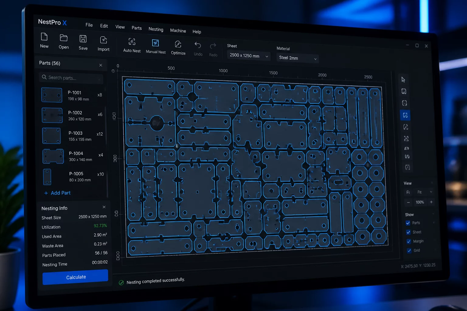
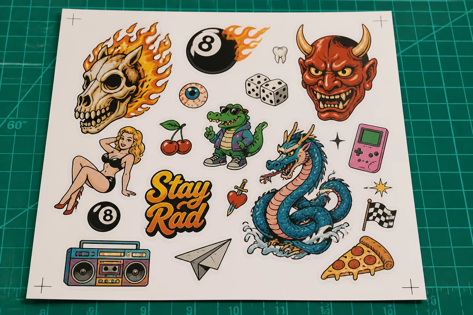
Finally, clarity on what Business Edition actually does for nesting workflows and margin calculations.