Why Orientation Constraints Matter in Real Cutting Jobs
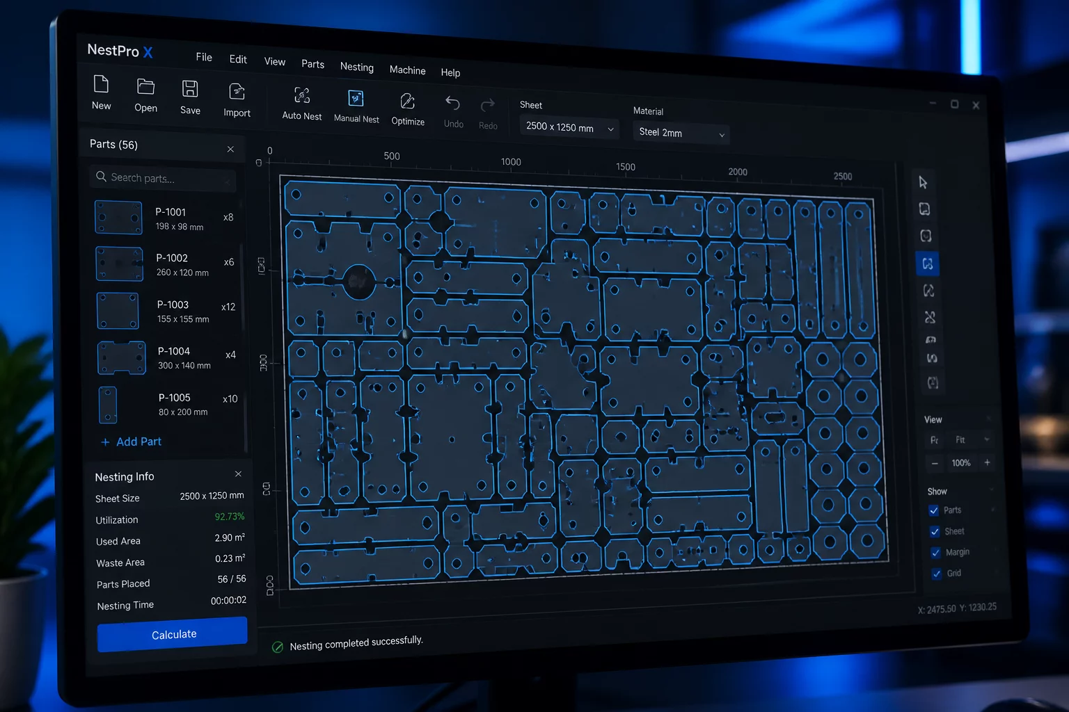
Silhouette Studio delivers sophisticated arrangement tools, particularly when using automated nesting utilities. Unchecked automation rotates vector objects at arbitrary angles to minimize scrap area. While this mathematical optimization fits more parts per square inch, physical materials impose non-negotiable optical and structural limits. Brushed metallic vinyl, wood veneers, textured cardstock, and directional heat transfer vinyl all exhibit light reflection patterns that change when rotated.
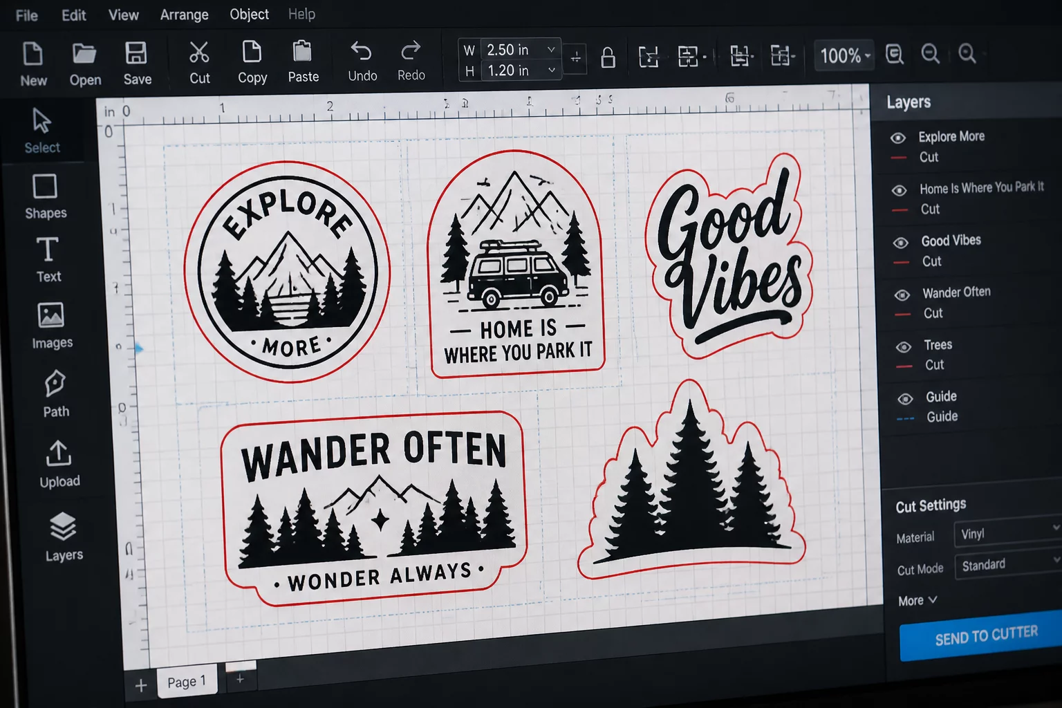
Rotating a typography decal 90 degrees might save two inches of sheet length, but applying that sticker alongside non-rotated elements reveals mismatched luster under ambient lighting. Enforcing strict orientation constraints prevents visual variance, eliminates grain misalignment in layered projects, and maintains predictable weed lines across multi-copy runs.
Anisotropic Stretch and Machine Feed Direction
Rolled media expands and flexes differently along the machine roller feed axis compared to the perpendicular cross-roller axis. Aligning long, thin shapes parallel to the feed direction prevents cut blade drag and carrier backing deformation.
Configuring Rotation Steps and Boundary Clearances
Inside Silhouette Studio, rotation rules can be assigned across the Nesting Panel, Object Transform palette, and Replicate tools. Selecting the appropriate constraint level depends entirely on the material classification and design geometry:
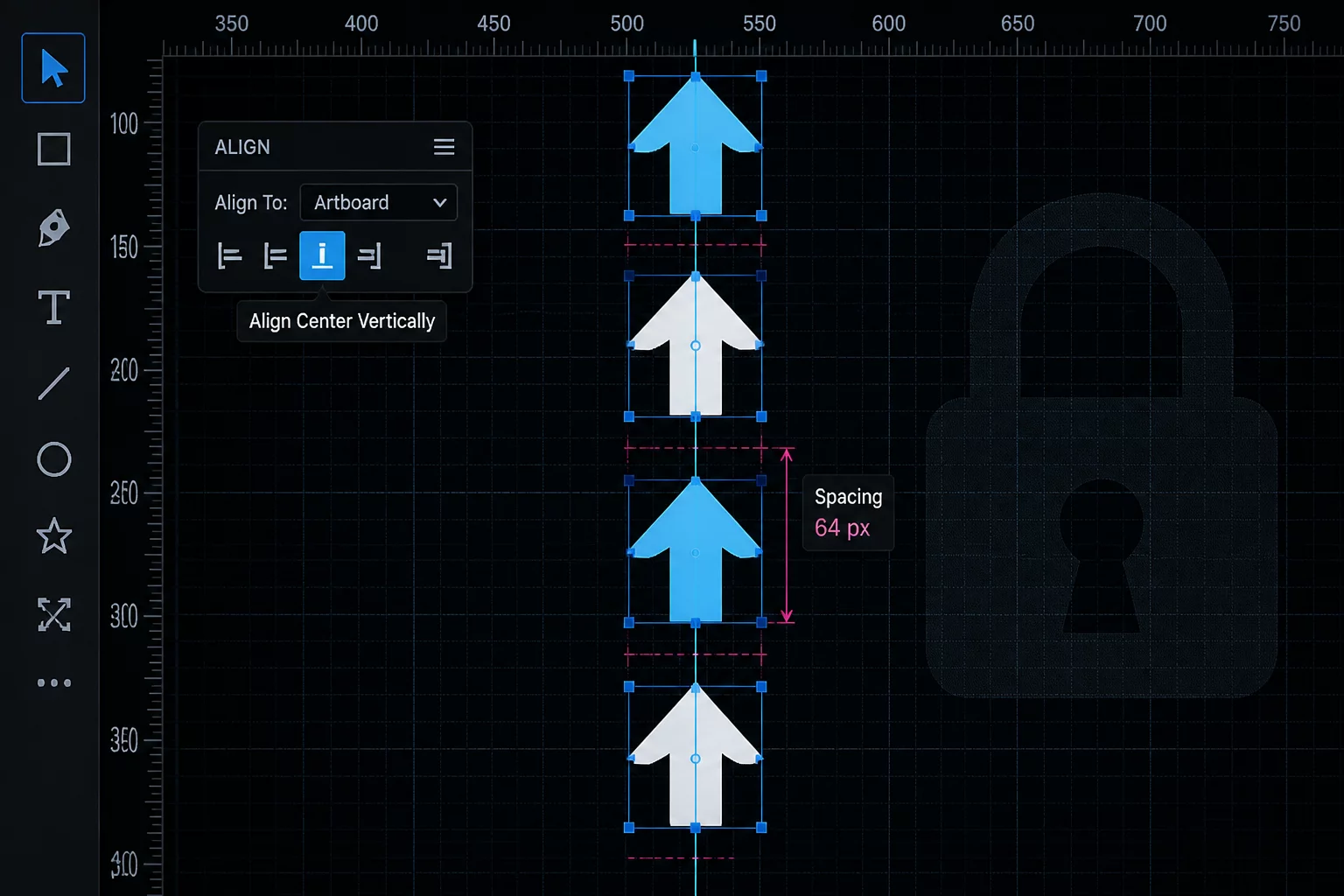
- Fixed 0° Lock (Maintain Orientation): Restricts all geometry to its initial design angle, crucial for patterned vinyl and directional logos.
- 180° Flip Restriction (2 Rotations): Permits upright and inverted placement while preserving vertical grain parallelism on symmetrical cutouts.
- 90° Orthogonal Steps (4 Rotations): Allows four right-angle placements for isotropic materials like smooth matte vinyl and untextured paperboard.
Pairing rotation locks with dedicated object padding parameters ensures that tight clusters leave sufficient weeding channels. Setting object spacing to at least 0.08 inches (2.0 mm) prevents blade over-travel from slicing neighboring paths when cutting high-density orientation-locked arrays.
Print & Cut Sensor Zone Awareness
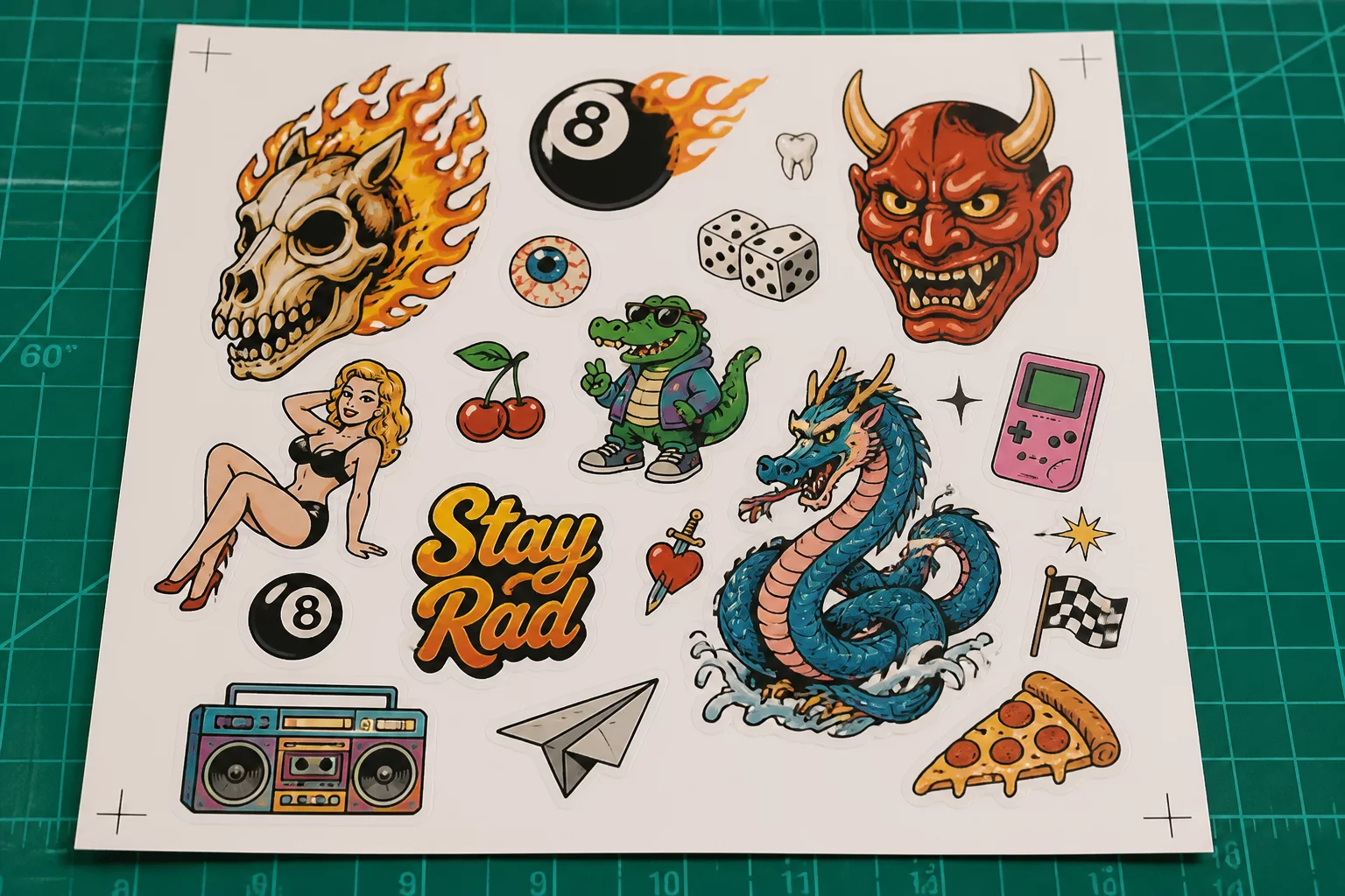
When working with Print & Cut documents, locking orientation is critical to keep artwork outside the optical registration mark crosshatch areas. A rotated element creeping into sensor boundaries causes read failures.
Step-by-Step Workflow for Grain-Sensitive Production Sets
To establish a predictable production layout, first group all sub-paths of each individual unit using Object > Group (Ctrl+G). This guarantees internal counter spaces stay locked to the outer perimeter contour. Open the Page Setup Panel, set your actual media dimensions, and define a safety margin of at least 0.25 inches around all active cutting boundaries.
Next, open the Nesting panel, select your target boundary, and choose 0° or 180° under the Rotations dropdown. Run the placement calculation and inspect the resulting layout. If empty pockets remain along the bottom or side margins, manually insert secondary isotropic parts (such as test swatches, brand labels, or small circular badges) to reclaim remnant space without compromising primary grain alignment.