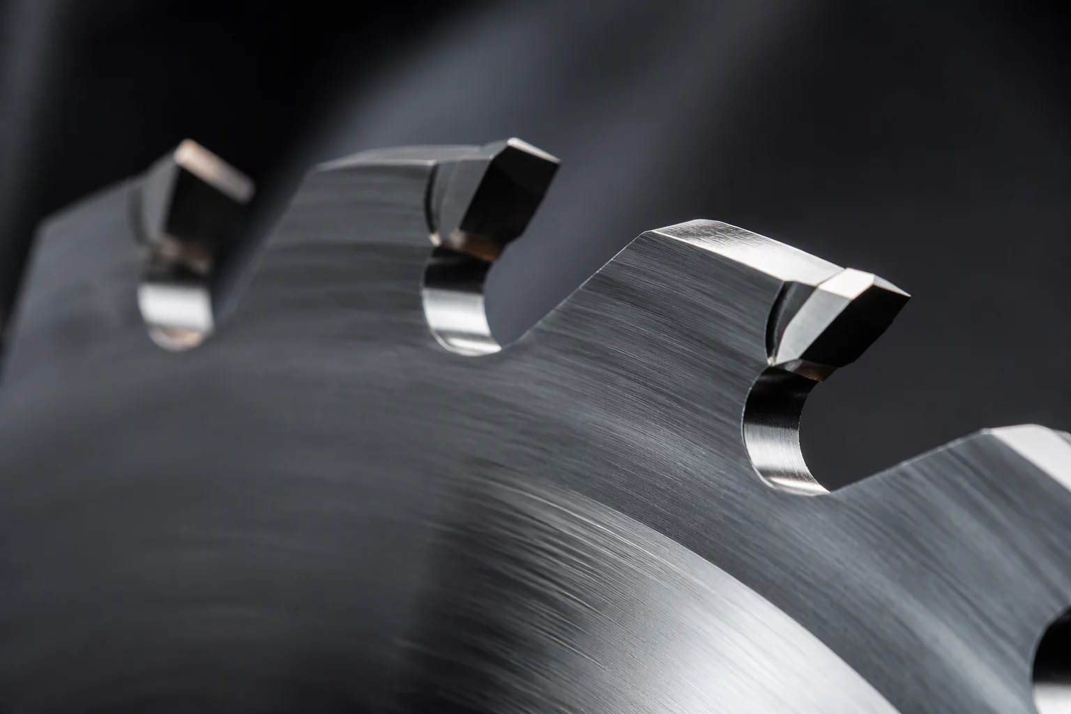
Overcoming High-Velocity Friction and Heat
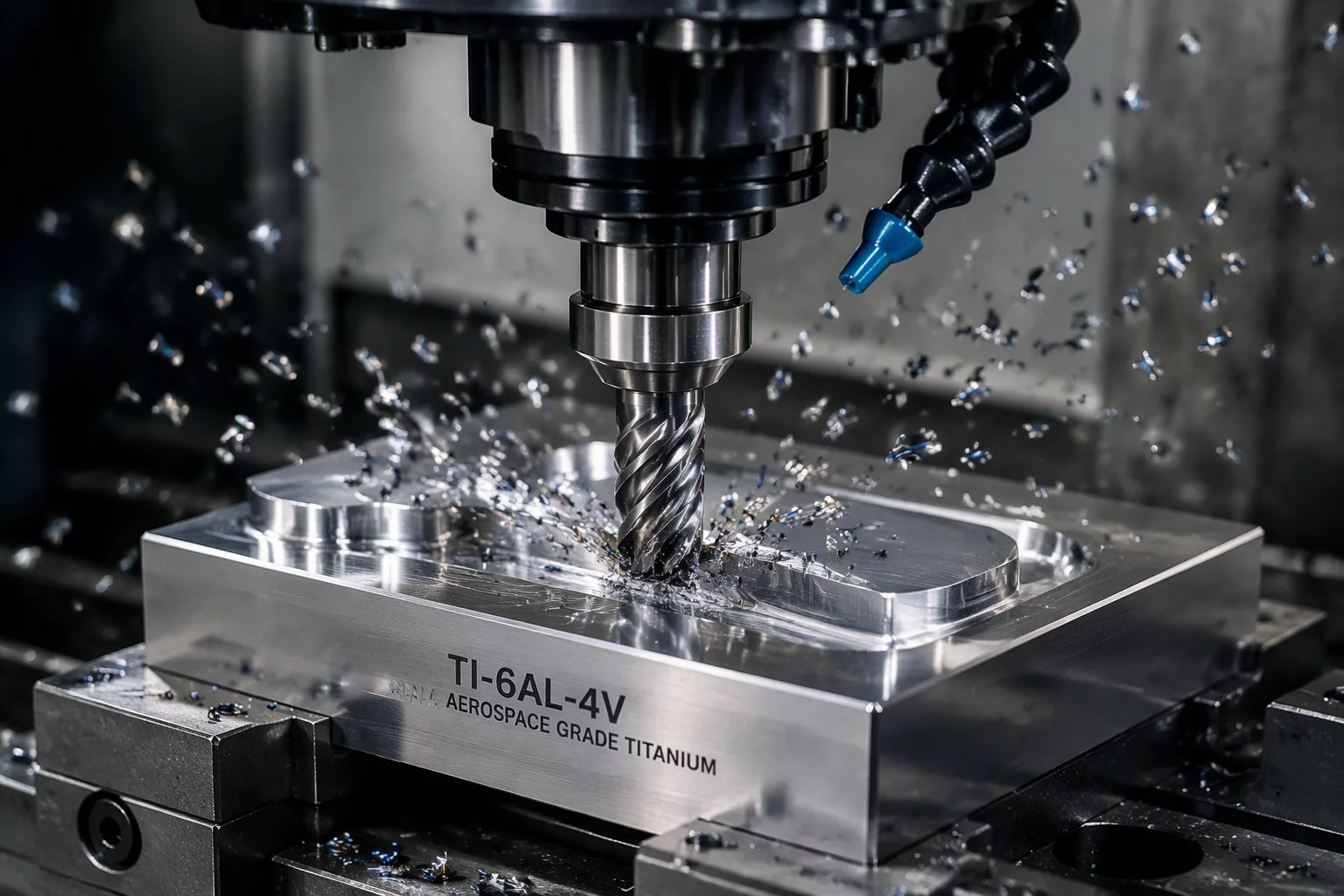
When industrial cutting equipment operates above 600 meters per minute, standard stock blades experience rapid thermal buildup along the shearing contact point. This friction leads to blade deflection, adhesive melting on synthetic films, and premature dulling across tight radius turns. Baucor's specialized manufacturing program addresses these challenges by developing tailored blade configurations made from sub-micron tungsten carbide, specialized ceramic matrix composites, and hardened tool steels designed specifically for high-velocity slitting, scoring, and contour slicing.
In continuous converting operations, edge degradation directly increases scrap rates. Microscopic burrs and frayed borders force operators to widen boundary safety margins between adjacent nested components, sacrificing raw material utilization. By calibrating the thermal conductivity and edge bevel angle to match the exact density of the substrate, these custom industrial blades maintain a surgical shear line across millions of linear cycles without thermal deformation.
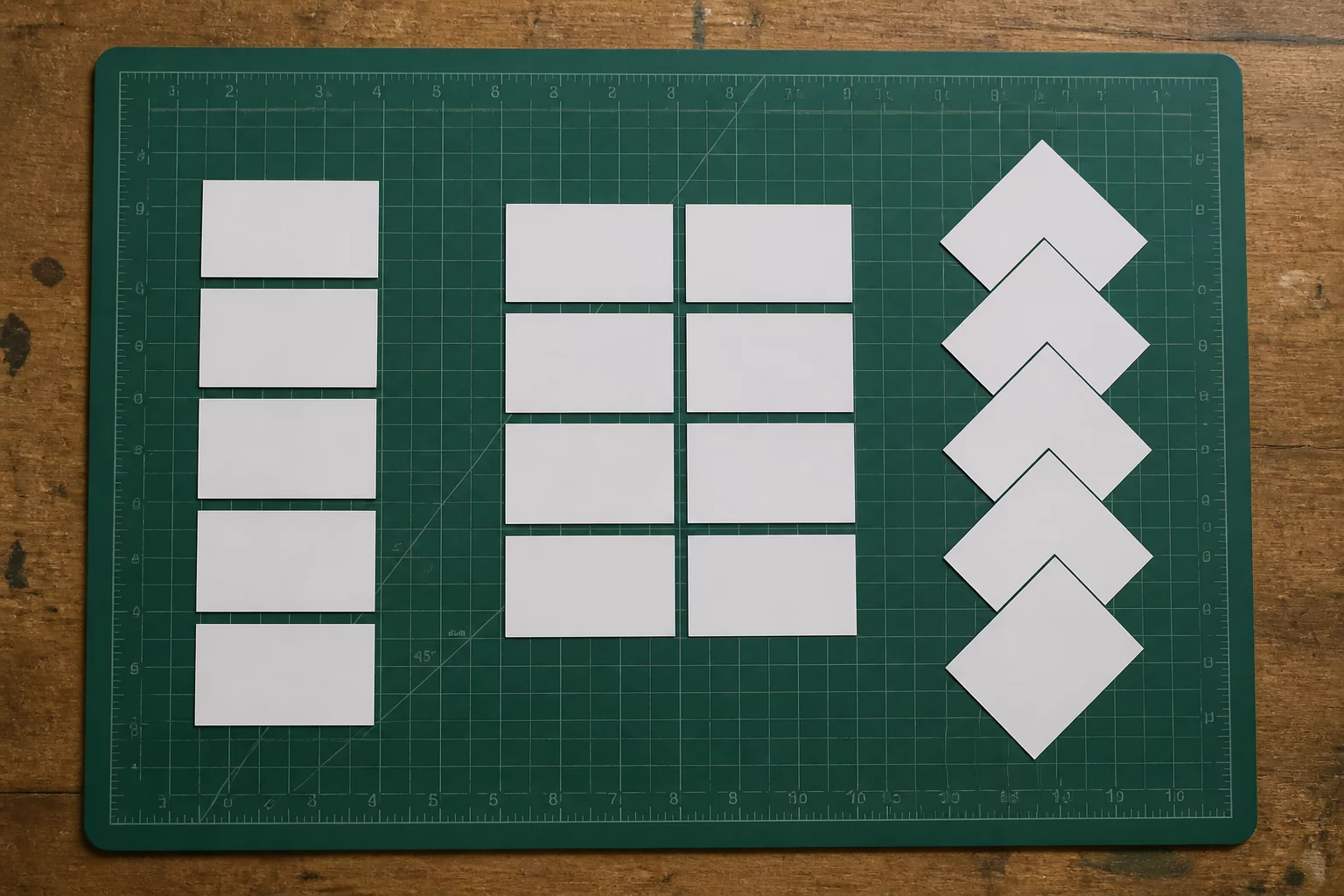
Compare placement, material direction, spacing, and post-cut handling using your actual pieces and sheet boundary.
Custom Geometry and Micro-Bevel Engineering
Achieving long-term dimensional precision in high-speed rotary and oscillating cutters requires purpose-built geometry rather than off-the-shelf universal profiles. Baucor achieves tight edge tolerances by pairing multi-axis CNC grinding with tailored coating technologies that prevent premature wear under severe mechanical stress:
- Sub-Micron Tungsten Matrix: Delivers Rockwell C hardness up to 92 HRC without micro-fracturing under lateral vibration during high-speed directional changes.
- Asymmetric Double-Facet Grinding: Decreases material displacement resistance during ultra-rapid web processing passes and eliminates feathering on flexible plastics.
- Physical Vapor Deposition (PVD) Coatings: Titanium carbonitride (TiCN) and diamond-like carbon (DLC) layers prevent adhesive sticking and thermal degradation on multilayer films.
Toolpath Dynamics and Material Yield Impact
In precision nested layouts, the physical blade thickness and the cutting kerf determine the minimum permissible bridge distance between adjacent shapes. When blades flex or suffer from lateral runout under feed pressure, software operators are forced to increase part-to-part margins from 1.5 mm up to 4.0 mm to prevent part collision or edge blowouts. Custom-rigidified blades engineered with reinforced back-ribs eliminate this deflection entirely.
With lateral blade displacement stabilized under high accelerations, cutting software can nest components closer together across the entire usable sheet width. Compare placement, material direction, spacing, and post-cut handling using your actual pieces and sheet boundary.
Integration into Automated Cutting Workflows
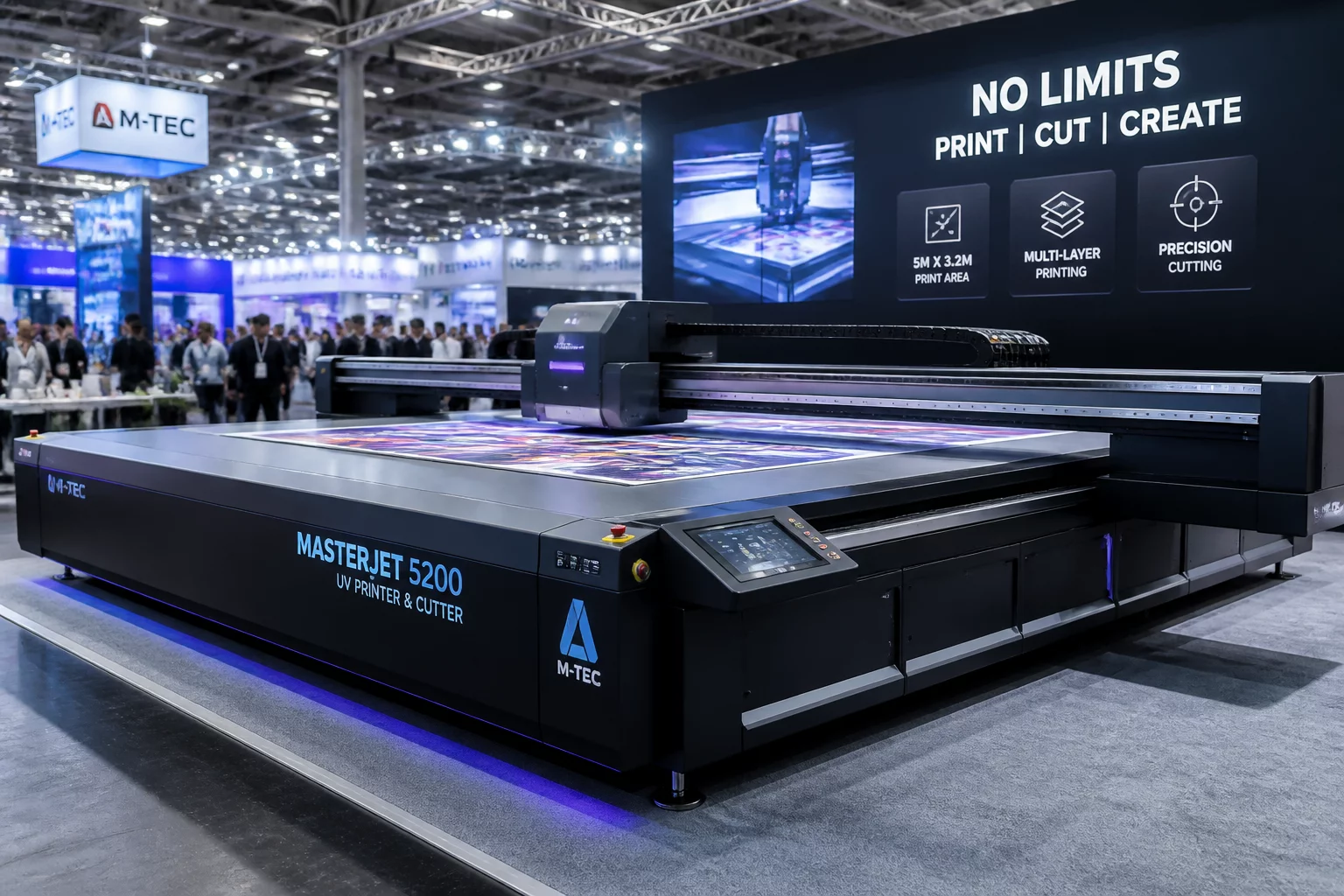
Deploying custom industrial blades into high-throughput flatbed cutters and automated roll-to-roll slitting systems involves aligning vector plunge feeds with the blade's entry rake angle. Operators who calibrate downforce pressure and lead-in tangency arcs to the blade's specific facet geometry experience zero skipped cuts and dramatically extended tool life, establishing dependable repeatability across continuous fabrication schedules.
Riley Brooks
Tooling Research LeadRiley Brooks evaluates advanced tooling systems, sheet nesting physics, and industrial cutting machinery parameters for digital fabrication workshops.