
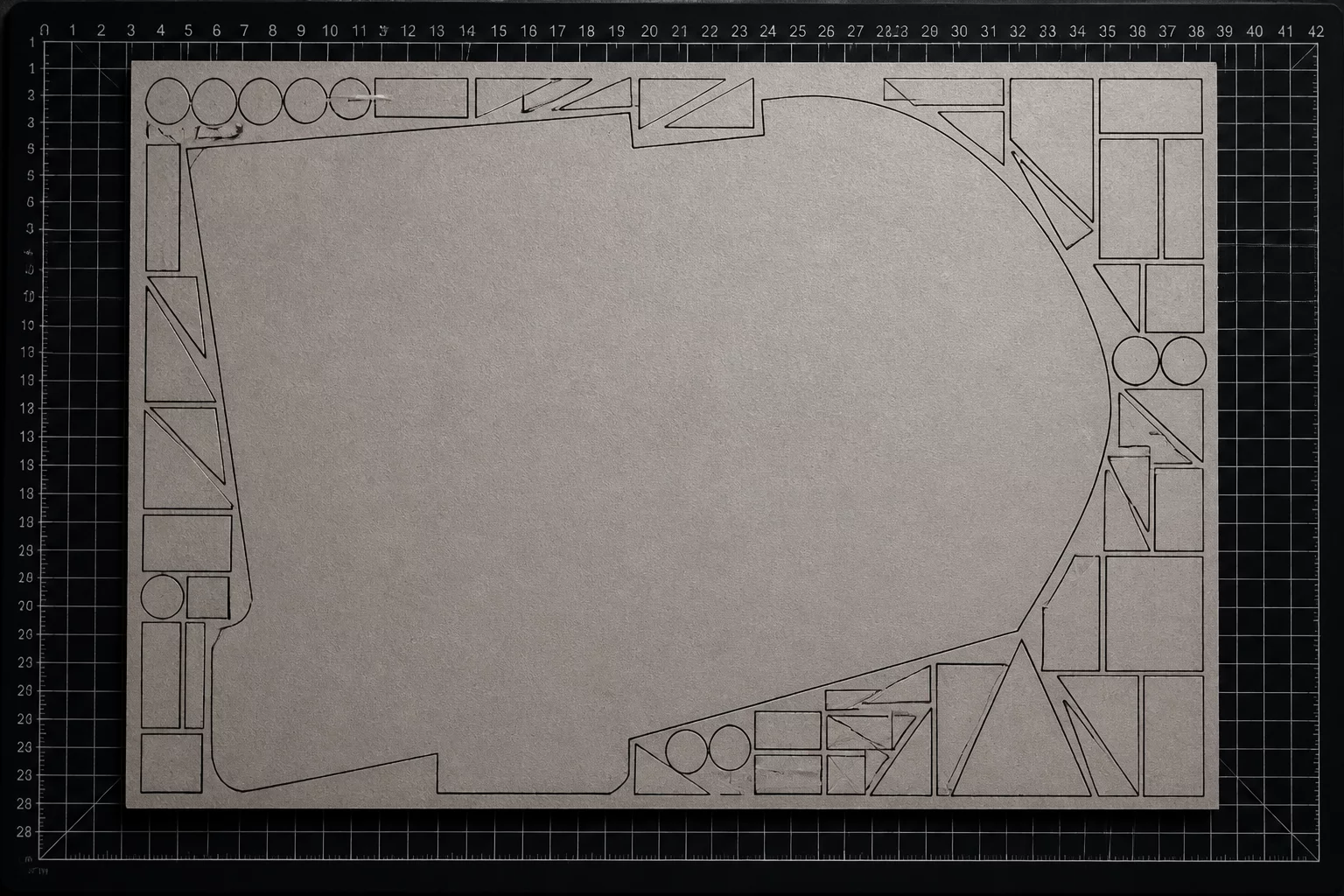
The Anchor Element Effect in Mixed-Scale Nesting
In flatbed cutting and plotter workflows, placing a single large silhouette instantly breaks symmetrical grid systems. The anchor piece dictates the primary orientation axis and consumes the central cutting envelope, leaving irregular perimeter zones. When operators attempt to treat the remaining negative space as standard margins, material yield drops drastically unless smaller parts are strategically fitted around its contours.
The primary challenge stems from aspect ratio collisions. A standard cutting bed handles repeating uniform shapes with predictable kerf spacing. Once an oversized element extends across major axis boundaries, it isolates corner patches that cannot house identical items. Recognizing this threshold early prevents accidental material waste and unnecessary blade travel overhead.
Explore interactive cutting challenges where mixed part sizes and rigid material constraints test real-world workshop yield.
Solving the Trapped Material Dilemma
Trapped material occurs inside concave boundaries or narrow perimeter corridors created by large contours. Rather than discarding these offcut areas as production scrap, workshop planners can assign secondary parts directly into the anchor piece's negative space.
-
1
Perimeter Alignment Priority: Align the longest straight edge of the large piece flush against the machine's primary datum margin to preserve contiguous offcuts.
-
2
Internal Negative Cavities: Fill inner hollows such as archways or loop centers with micro-components before distributing parts to sheet perimeters.
-
3
Blade Direction and Kerf Pressure: Cut internal nested details first to maintain rigid structural grip before releasing the outer boundary of the master piece.
When executing these mixed-scale layouts, sequence control is vital. Modern cutting plotters risk shifting flexible media if the master outline separates prematurely. By programming the software toolpath to process internal smaller pieces prior to tracing the large perimeter, machine grip remains constant across the entire cutting mat.
Key Takeaway: Anchor First, Fill Inwards
Always anchor oversized geometries along fixed baseline margins and prioritize inner cutouts for secondary items before committing outer perimeter cuts. Compare placement, material direction, spacing, and post-cut handling using your actual pieces and sheet boundary.
Common Questions on Large Piece Nesting
Further Layout Case Studies
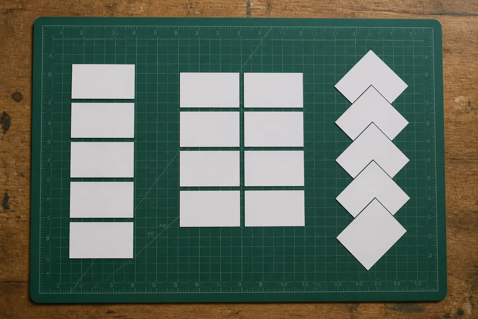
Ten Labels, Three Layout Strategies
Analyze how three distinct nesting layouts for ten packaging labels affect weeding speed, kerf clearance, and total sheet yield.
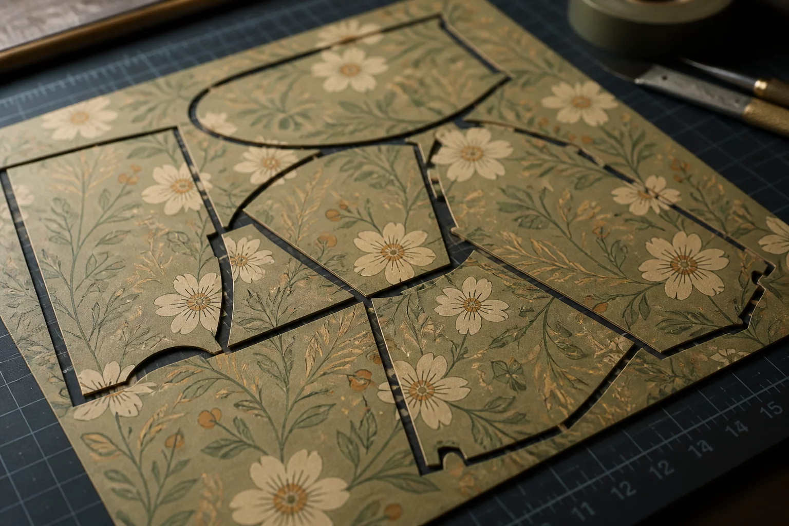
When Rotation Saves Space but Changes Orientation
Evaluating the trade-offs between dense geometric nesting and maintaining material grain or pattern alignment across cut components.
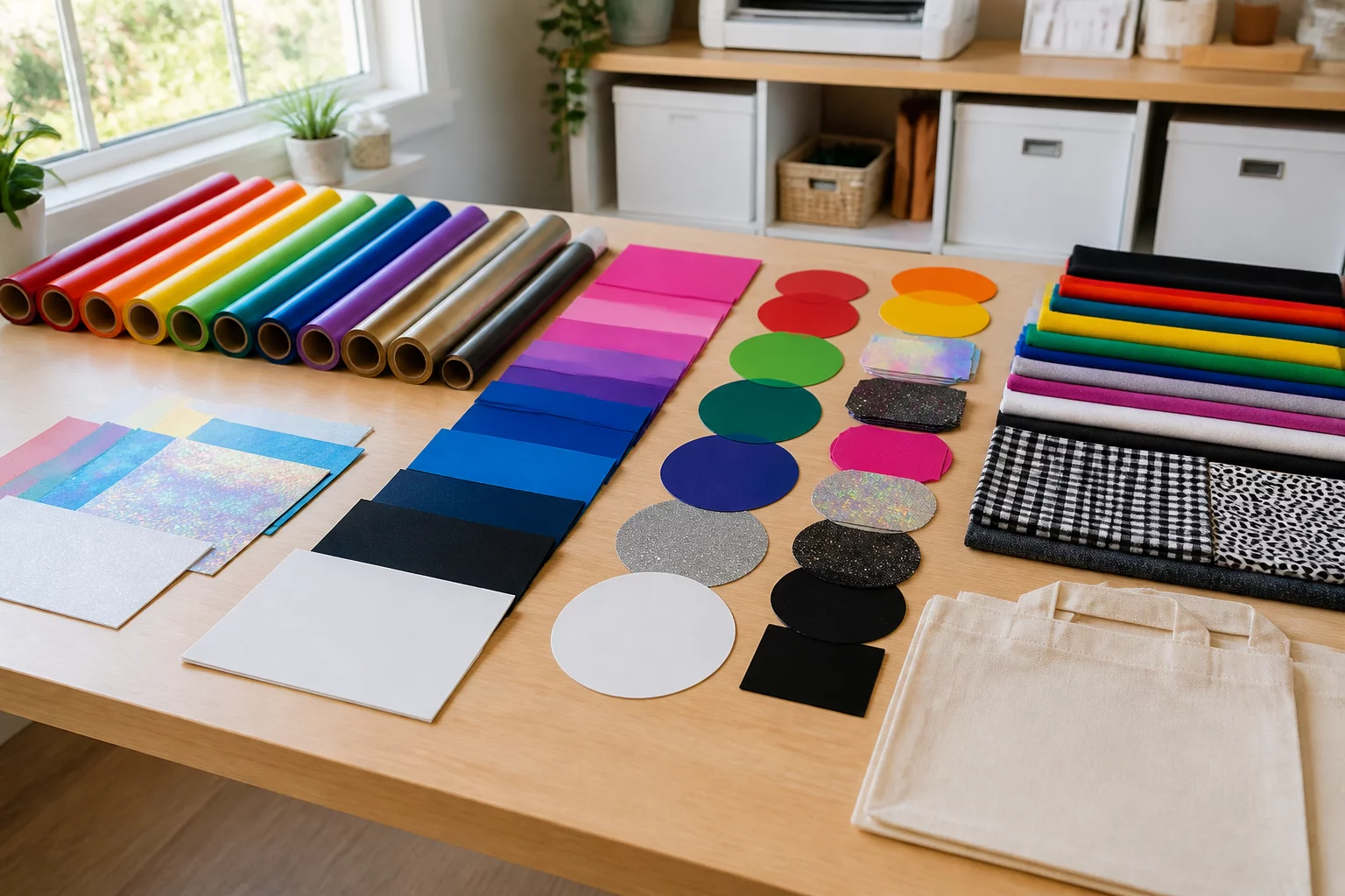
Group by Design or Group by Material?
Determining whether production efficiency benefits more from cutting full design kits together or batching by identical substrate rolls.
Workshop Feedback & Notes
No comments yet. Be the first to leave a note or observation about this layout study.
Leave a Comment or Observation
Share your cutting tests, nesting challenges, or workflow feedback.